Use Digital Iteration to Avoid the Wrong Physical Build
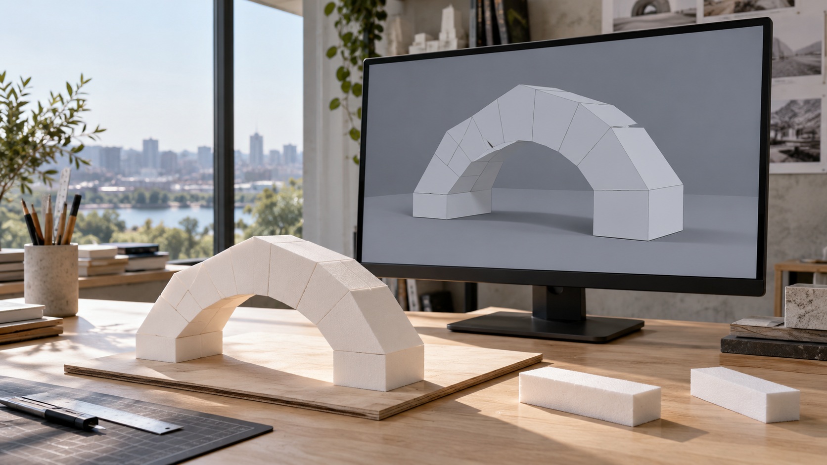
A digital prototype saves material only when it replaces an avoidable physical mistake or improves the object that eventually gets made. Producing dozens of attractive renderings does not by itself reduce waste, and an unverified model can send the same error directly into a cutting machine. The useful transition from prototype to production is therefore a sequence of increasingly specific questions: Is the silhouette right? Does it fit the route? Can the modules assemble? Will the chosen process retain the required detail? Which uncertainty still needs a physical test? Answer broad geometry questions digitally, test material behavior physically, and keep the accepted design traceable through both. This approach can reduce discarded foam, repeated machining, unnecessary coatings, and emergency shipping without pretending that a screen image proves performance. The goal is to build fewer wrong things, not to remove every prototype from a craft that still depends on real materials and hands-on judgment.
A: No. Units, geometry, process access, fixtures, interfaces, and export requirements still need verification.
A: The information needed to answer the current decision, usually major dimensions and relationships before surface decoration.
A: No. Material, coating, joint, and handling uncertainties often need representative physical evidence.
A: It reduces presentation differences that can disguise the actual geometric comparison.
A: A stable physical boundary with traceable dimensions and revision information future teams can trust.
A: Not if it compromises support, allowance, or edge quality and increases rejects.
A: Coordinate purchases with design certainty, separating stable requirements from unresolved detail materials.
A: A replacement from an earlier nominal file may otherwise fail to match the accepted physical assembly.
A: Only with a justified baseline; an unbuilt hypothetical is not automatically observed avoided material.
A: A bounded documented outcome such as a verified recut avoided, with assumptions and measurement limits stated.
Decide Which Question Each Model Answers
A silhouette model can remain simple. It needs the main masses, proportions, and intended viewpoints, not a detailed texture map. A clearance model needs the envelope of the finished object, packaging, supporting equipment, and the route. A fabrication model needs interfaces and geometry appropriate to the actual process. Mixing these purposes too early can slow useful decisions while creating false confidence in details nobody has checked.
Write the current question beside the model revision. If the task is to compare three neck poses for a sculpture, do not spend the review discussing speculative paint scratches. If the task is to verify a crate opening, a realistic background render adds little. Keeping the question explicit lets the team decide what evidence is sufficient and when it is time to move on.
Preserve rejected alternatives only when their reasons remain useful. A named option with a short note about blocked sightlines or excessive transport width can prevent the same mistake later. An anonymous folder of nearly identical files does not provide that benefit. Organize the decision history around why choices changed, not merely the order in which files were saved.
Establish Units and Real Dimensions First
Choose a consistent unit system and verify a few known measurements when importing drawings or geometry. Check the object’s overall width, height, and depth against the approved brief. Imported assets can contain scale or orientation assumptions that are easy to overlook in a persuasive viewport. A model that looks correct relative to itself can still be wrong for the room, stock, or transport vehicle.
Use a simple dimensional reference in every major scene: a known doorway, scale person, base outline, or measured fixture. Keep the reference tied to actual project information rather than a decorative stock asset. Distinguish confirmed venue dimensions from estimates. A clearance decision based on an unverified room model should remain open until reliable measurements are available.
Compare Alternatives Under the Same Conditions
Keep camera position, scale, lighting, and reference objects consistent when comparing design options. Otherwise a dramatic lens or flattering light can make one variant seem better for reasons unrelated to its geometry. Use plain views alongside presentation renders. Front, side, and plan comparisons often reveal proportion changes more clearly than one atmospheric perspective.
Compare the whole assembly, not just its most photogenic face. Show the rear, the base, module boundaries, and important negative spaces. A concept may look compact from the front while requiring an impractical projection behind it. Digital rotation is especially valuable here because it exposes those relationships before a large blank has been assembled.
Evaluate alternatives against agreed criteria such as visibility, route envelope, material allowance, connection access, and intended reuse. Do not invent an environmental score when the underlying quantities are unknown. A variant can be described accurately as using a smaller planned stock envelope without claiming that it has the lowest complete footprint.
Record the accepted option with the people authorized to approve it. A fabrication team should not proceed from a model that was approved only for artistic direction while unresolved dimensions remain. Identify which decisions are frozen and which remain provisional. This makes later revision possible without allowing an informal change to erase an important earlier agreement.
Design the Module Interfaces Before Detail
Locate where the object divides for transport, handling, assembly, maintenance, and replacement. Show actual access to the connections, including the space needed by hands and tools. A connector may fit in a digital cavity while remaining unreachable after neighboring parts are installed. Simulate the assembly order rather than inspecting only the final closed model.
Separate locating geometry from the designed fastening function. Add the intended clearances and finish allowances, then check the relationship in the production representation. Foam compressibility should not become the plan for resolving every mismatch. A forced fit can damage a coating or hide a misplaced reference that later complicates replacement.
Use common interface definitions for interchangeable parts. If a seasonal display will receive new decorative modules, retain the mounting boundary and document its revision. This can reduce repeated base fabrication, but only when later designers can find and trust the interface information. Reuse is an information-management problem as well as a material-design problem.
Distinguish Visual Geometry From Manufacturing Geometry
A rendered surface can hide thin walls, intersecting shells, disconnected pieces, or details too small for the selected process. Inspect the underlying geometry and the output requirements of the fabrication software. Check that scale, orientation, mesh quality, and exported boundaries survive transfer. A beautiful shaded view is not evidence that a toolpath or cutting template is ready.
Simplify irrelevant detail before manufacturing while preserving the accepted silhouette and important features. A distant scenic surface may not need the dense geometry used for a close-up render. Keep a controlled production version rather than overwriting the design source. The distinction lets the team revise the art without losing the specific representation that generated accepted parts.
Review the actual material envelope and process access. A deep narrow recess may exceed cutter reach; a sharp internal corner may require another method; a projecting detail may be impractical in one piece. Resolve those constraints through the intended machine and tooling information. Do not let the software’s ability to display a shape imply that the available equipment can fabricate it unchanged.
Where machining is used, simulate the stock removal and the complete tool assembly, not just the cutting tip. Include fixtures and remaining stock where the software supports that review. Simulation can reduce avoidable collisions and wasted blanks, but it remains dependent on correct setup information. Verify the real origin, tool, fixture, and stock before production begins.
Use Physical Tests Where Digital Evidence Ends
Material behavior belongs in representative samples. Foam edge quality, adhesive compatibility, coating buildup, sheen, texture retention, and the behavior of a handled joint cannot be established by a rendering. Choose a small coupon that contains the uncertainty instead of building a miniature version of the entire object by habit. This concentrates material use on a decision the sample can genuinely answer.
Keep the test’s limits clear. A finish coupon can establish appearance under selected light without proving outdoor durability or structural capacity. A small alignment model can explain assembly without validating a full-size support. Obtain the appropriate qualified assessment where the project requires it. Digital iteration should make the remaining physical questions clearer, not make them disappear through presentation polish.
Nest and Order After the Design Is Stable Enough
Plan stock use with the actual part geometry, allowances, and workholding needs. Leave necessary space around fragile edges and fixtures. A tightly packed visual nest may consume less sheet area on screen while producing more damaged parts in practice. Compare accepted usable output rather than only the percentage of a rectangle covered by shapes.
Identify large reusable offcuts in the layout. Give them dimensions and material identifiers so the shop can store them as useful stock rather than anonymous waste. Where practical, sequence cuts to preserve those pieces intact. The digital plan should survive unloading through a simple physical marking and storage procedure.
Time purchases around the level of design certainty. Ordering all expensive stock before module dimensions are accepted can force later compromises or generate leftovers. Conversely, delaying every purchase may create emergency freight. Use the decision schedule to distinguish stable bulk requirements from uncertain detail materials. The aim is coordinated ordering, not an inflexible rule that everything waits until the last drawing is perfect.
Keep Production Files Traceable
Issue a clear production package containing the accepted revision, units, overall dimensions, module identifiers, interfaces, material assumptions, and unresolved exclusions. Link each exported file to that package. A folder name such as final-new-latest does not reliably communicate authority when several people are working at once. Use a version convention the whole team understands.
Archive the files that actually produced accepted parts, including any approved shop adjustments. If a carver changed an interface or a programmer compensated for a process limitation, capture that information before it becomes tribal knowledge. A future replacement made from an earlier nominal model may otherwise fail to match the physical assembly everyone considered finished.
Protect unchanged components during revision. Show what changed and what did not, then review the affected interfaces. Recutting a complete object for a local approved change wastes material and can introduce new discrepancies elsewhere. Modular production information makes selective replacement possible when the physical design also supports it.
Do not automate every decision merely because the software allows it. Human review remains important for intended use, visual hierarchy, access, and ambiguous source information. Use automated checks for clearly defined relationships and keep their assumptions visible. A passing file check should mean that a specific condition passed, not that every aspect of the project has been approved.
Record the Avoided Work Honestly
Compare the accepted production outcome with a meaningful baseline. Useful quantities include discarded foam, number of full-size recuts, coating consumed during rejected trials, freight changes, and labor spent correcting mismatches. Keep estimated avoided work separate from material actually measured. A hypothetical rejected design should not automatically be counted as a saved physical prototype.
Digital work has its own equipment, time, and energy demands, so avoid claiming it has no footprint. Often the practical case for it is straightforward without a universal percentage: one verified clearance problem corrected before fabrication can prevent a documented rebuild. Report that bounded result and the conditions. Keep project notes that let the next team repeat the successful decision process rather than only admire the final render.
Close Each Decision Before Reopening Detail
Give review comments an owner and a disposition. A note about a blocked connection should not disappear into a presentation chat while the next model adds decorative resolution. Record whether the issue was corrected, accepted with a limitation, or left open.
After a major revision, return to the relevant earlier check. Moving a wing may improve silhouette while increasing the packed width; changing a base may reopen handling access. The decision history helps identify which checks the alteration actually affects.
Keep the final review focused on unresolved questions rather than repeating every settled preference. A short clear list makes it easier to find the issue that could still waste a full-size blank or prevent the object from reaching its installation position.
Prototype the Uncertainty, Not Everything
Digital iteration is most valuable when it resolves geometry early and directs physical testing toward real material unknowns. Preserve accepted revisions, validate manufacturing information, and measure the work genuinely avoided. Fewer wrong builds matter more than a larger collection of polished previews.